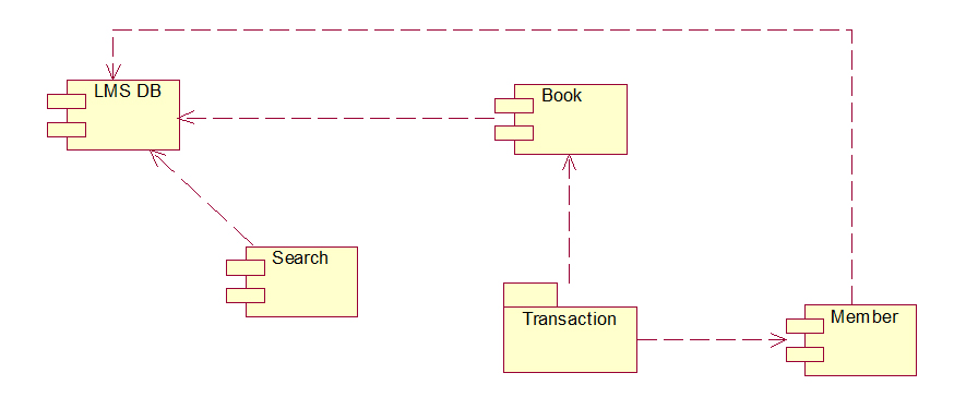
Component Diagrams depict the structural relationship between software system elements and help us in understanding if functional requirements have been covered by planned development. Component Diagrams become essential to use when we design and build complex systems.
What Is The Difference Between The Class And Component Diagram In Uml Quora
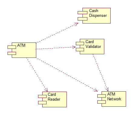
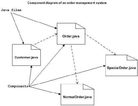
In this approach component diagrams allow the planner to identify the different components so the whole system does what its supposed to do.
Component diagram gfg. Basic components of a statechart diagram. Using set it can be represented as Every student in Student Entity set is participating in relationship but there exists a course C4 which is not taking part in the relationship. Every oval shape represents one attribute and is directly connected to its entity which is in the rectangle in shape.
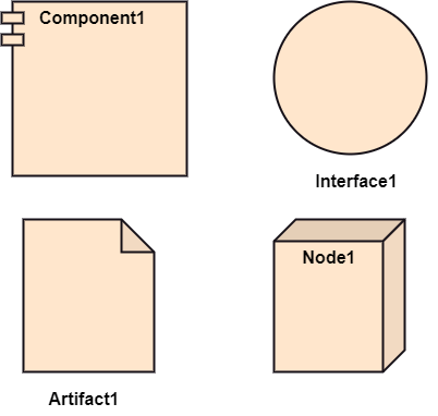
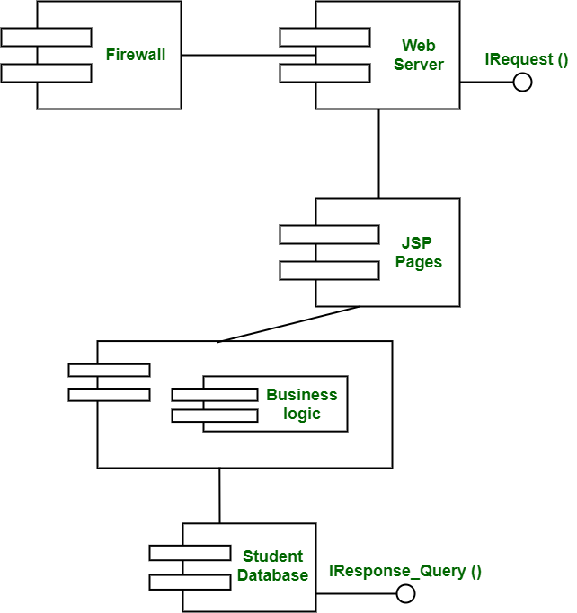
Graphically a component diagram is a collection of vertices and arcs and commonly contain components interfaces and dependency aggregation constraint generalization association and realization relationships. Components of a ER Diagram. The diagram depicts the Enrolled in relationship set with Student Entity set having total participation and Course Entity set having partial participation.
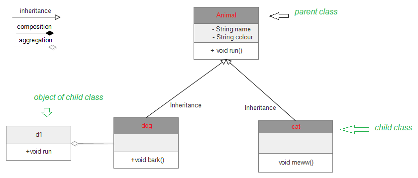
As shown in the above diagram an ER diagram has three main components. When we implement Generalization in a programming language it is often called Inheritance instead. Open a blank document in the class diagram section.
From the library select the class diagram and click on create option. An attribute in an Entity-Relationship Model describes the properties or characteristics of an entity. The UML diagrams Generalization association is also known as Inheritance.
After editing according to requirement save it. These are as follows. There are several diagram components that can be efficiently used while makingediting the model.
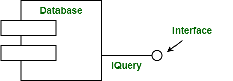
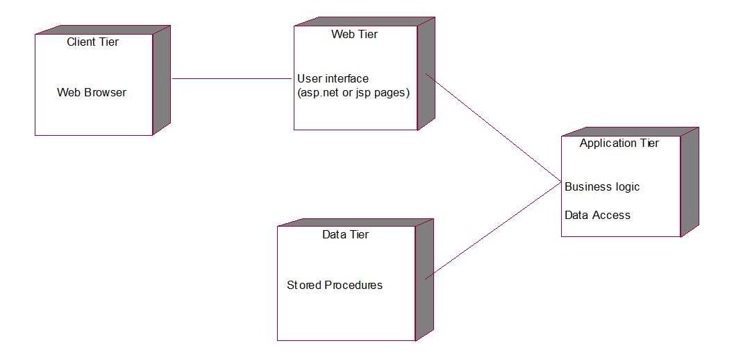
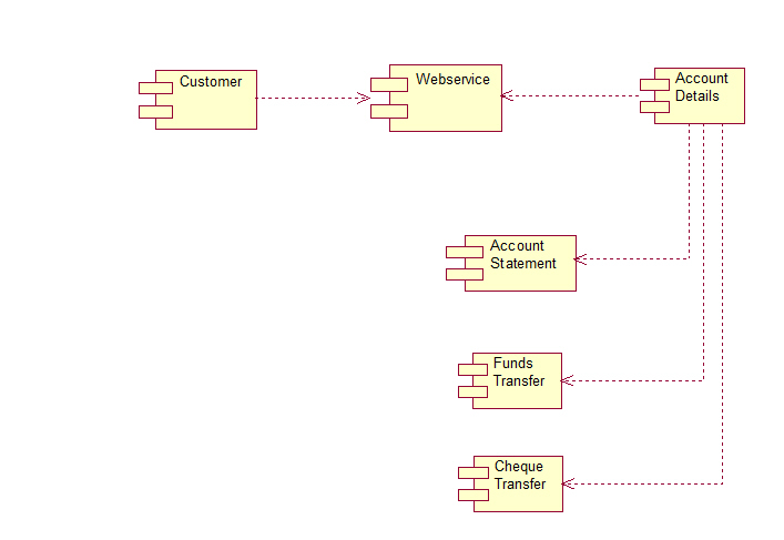
Component diagram shows components provided and required interfaces ports and relationships between them. The components for switching the sensor are mounted on the printed circuit board. Prepare the model of the class on the opened template page.
An entity is represented as rectangle in an ER diagram. In the ER diagram a weak entity is usually represented by a double rectangle. More commonly in an OO programming approach the component diagram allows a senior developer to group classes together based on common purpose so that the developer and others can look at a software development project at a high level.
The terminology just differs depending on the context where it is being used. Transition We use a solid arrow to represent the transition or change of control from one state to another. Generalization and inheritance are the same.
Flume- Flume component is used to gather and aggregate large amounts of data. The transmitter must be connected to the controller in accordance with the terminal diagram see Connectors. Initial state We use a black filled circle represent the initial state of a System or a class.
Figure initial state notation. It is represented by an oval or ellipse shape in the ER diagram. Apache Flume is used for collecting data from its origin and sending it back to the resting.
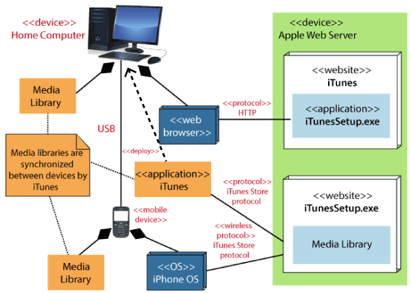
GfG will be pleased to advise you about suitable measures. We use them for modelling implementation details. This type of diagrams is used in Component-Based Development CBD to describe systems with Service-Oriented Architecture SOA.
An entity is an object or component of data.
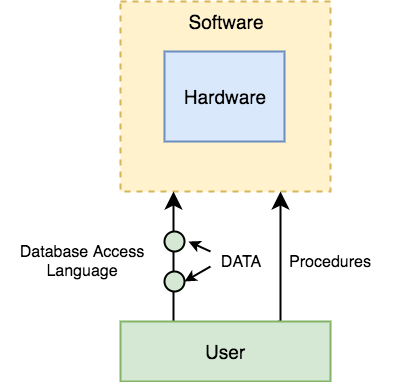 Components Of Dbms Database Management System Studytonight
 Component Diagram Tutorial Lucidchart
 Uml Deployment Diagram Javatpoint
Component Based Diagram Geeksforgeeks
 Uml Component Diagrams Tutorialspoint
 Deployment Diagram Tutorial Lucidchart
 Component Diagram Tutorial Lucidchart
 Uml Deployment Diagram Javatpoint
 Component Diagram Tutorial Lucidchart
 Component Diagram Tutorial Lucidchart
What Is The Difference Between The Class And Component Diagram In Uml Quora
 Deployment Diagram Tutorial Lucidchart
 Component Model Of A Simple Application Download Scientific Diagram
 Component Based Diagram Geeksforgeeks
 Unified Modeling Language Uml Class Diagrams Geeksforgeeks


0 Commentaires