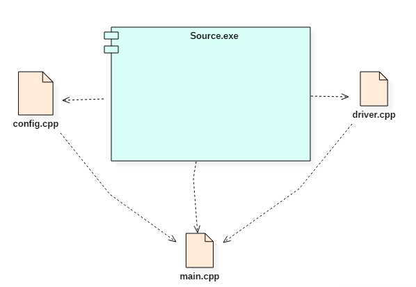
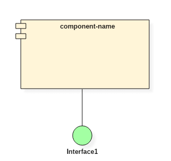
This is the main component as this is the program which controls everything. Composite Structure Diagram is one of the new artifacts added to UML 20.
 Kubernetes Tutorial For Beginners Basics Features Architecture
UML TutorialUML Unified Modeling Language is a standard language for specifying visualizing constructing and documenting the artifacts of software systemsUML was created by the Object Management Group OMG and UML 10 specification draft was proposed to the OMG in January 1997.

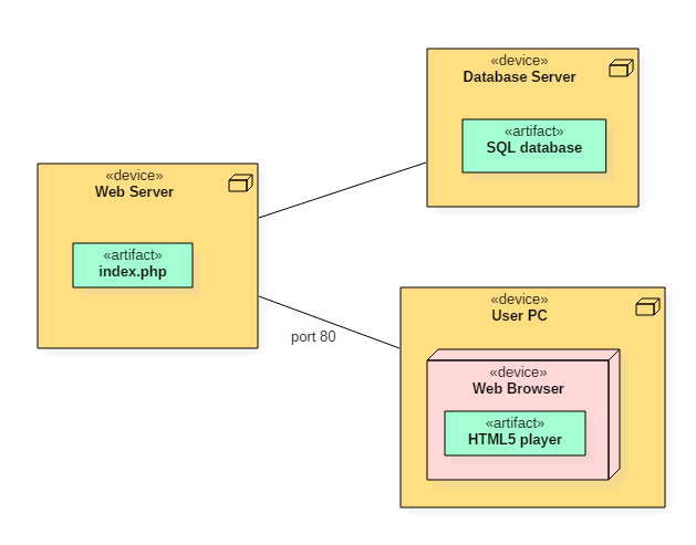
Component diagram guru99. Communication Diagrams are similar to Sequence Diagrams but are used instead to display the way in which the object interacts with other objects. Guru99 is totally new kind of learning experience. Map deployment of objects The Software Architect can use deployment diagrams to provide a static view of the run-time configuration of processing nodes and the components that run on the nodes.
MapReduce is a computational model and software framework for writing applications which are run on Hadoop. These MapReduce programs are capable of processing enormous data in parallel on large clusters of computation. The following diagrams are static diagrams.
The nine diagrams are divided into static diagrams and dynamic diagrams. The DBMS software is more like a wrapper around the physical database which provides us with an easy-to-use interface to store access and update data. 32 What is process flow diagram.
ER diagrams are created based on three basic concepts. In other words ER diagrams help to explain the logical structure of databases. Component-based development techniques consist of non-conventional development routines including component evaluation component retrieval etc.
The following diagrams are dynamic diagrams. Static Diagrams Also called Structural Diagram. Class diagram Object diagram Component Diagram Deployment diagram.
Below diagram shows various components in the Hadoop ecosystem-Apache Hadoop consists of two sub-projects Hadoop MapReduce. Entities attributes and relationships. ER Diagram stands for Entity Relationship Diagram also known as ERD is a diagram that displays the relationship of entity sets stored in a database.
It is important that the CBD is carried out within a middleware infrastructure that supports the process for example Enterprise Java Beans. A composite structure diagram is a UML structural diagram that contains classes interfaces packages and their relationships and that provides a logical view of all or part of a software system. The basic architecture of the Net framework is as shown below.
Dynamic Diagrams Also called Behavioral Diagrams. Net Framework ArchitectureNet Framework Architecture is a programming model for the Net platform that provides an execution environment and integration with various programming languages for simple development and deployment of various Windows and desktop applications. It consists of class libraries and reusable components.
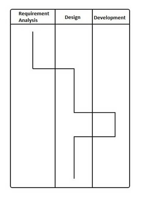
A process flow diagram is a sketch which describes major equipment plant streams and key central loops show the relationship between system components.
 Aggregation Vs Composition In Uml Key Differences
 Mvc Vs Mvvm Key Differences With Examples
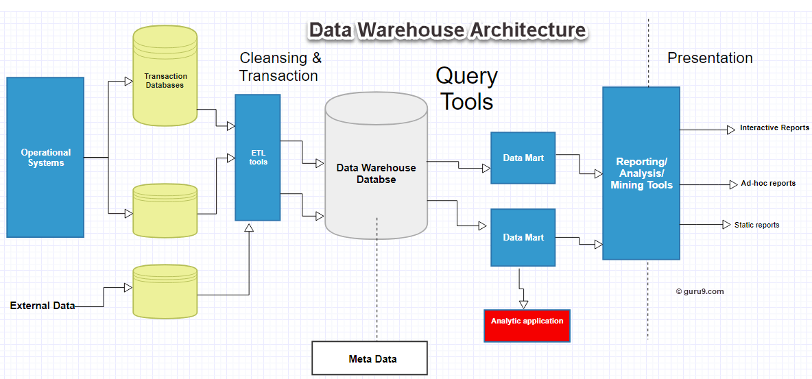 Data Warehouse Architecture Concepts And Components
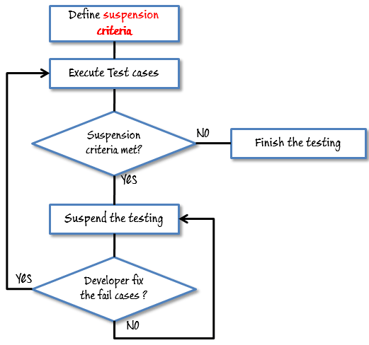 Test Plan What Is How To Create With Example
 Aggregation Vs Composition In Uml Key Differences
 What Is Net Framework Explain Architecture Components
 Model Based Testing Tutorial What Is Tools Example
 Uml Diagram Cheat Sheet And Reference Guide
 What Is Selenium Introduction To Selenium Automation Testing
Uml Diagram Cheat Sheet And Reference Guide
 Drools Tutorial Architecture Of Drools Rule Engine And Example
 Data Warehouse Architecture Concepts And Components
 Uml Diagram Cheat Sheet And Reference Guide
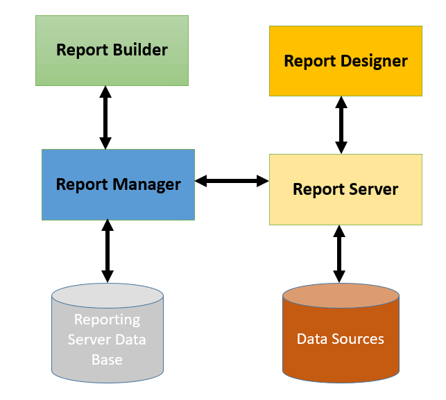 Sql Server Reporting Services Ssrs Tutorial For Beginners
 Uml Diagram Cheat Sheet And Reference Guide
 Uml Diagram Cheat Sheet And Reference Guide
 Uml Diagram Cheat Sheet And Reference Guide
 What Is Hp Loadrunner Testing Tool Architecture Components
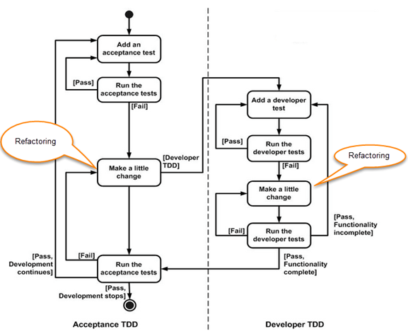 What Is Test Driven Development Tdd Tutorial With Example


0 Commentaires