It may also contain notes and constraints. Select Component in Toolbox.
 Component Diagram Tutorial Lucidchart
In UML 11 a component represented implementation items such as files and executables.
Component diagram rules. There can be multiple data flows between one entity and a process. Data flow must be from entity to a process or a process to an entity. The component diagram shows the relationship between software components their dependencies communication location and other conditions.
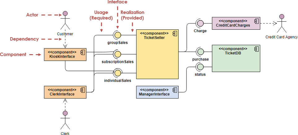
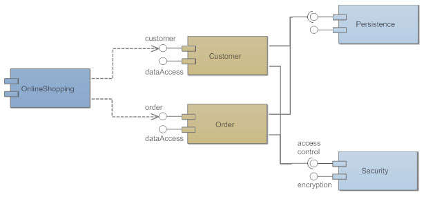
Dependency Generalization Realization Association Aggregation Composition Usage. Dependency Association Aggregation Composition Usage. They can be used to model the applications of an organization including their Provided and Required Interfaces and the information that is exchanged between the interfaces.
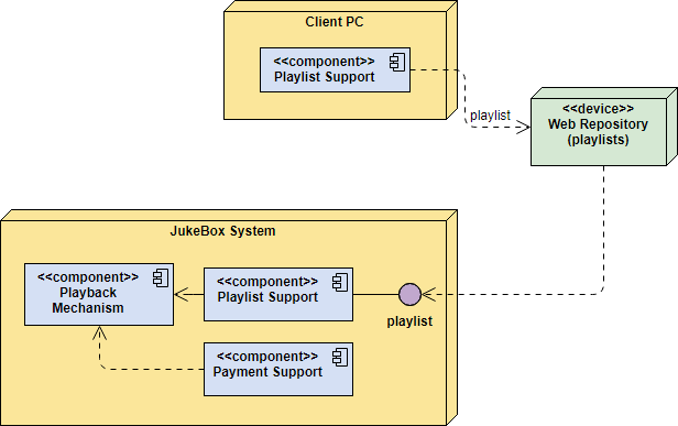
A component may be something like an ActiveX control - either a user interface control or a business rules server. The lines between components are often referred to as connectors the implication being that some sort of messaging will occur across the connectors. A component diagram also known as a UML component diagram describes the organization and wiring of the physical components in a system.
If one of the bulbs is broken then current. Or a hardware component such as a circuit microchip or device. Data can not flow between two entities.
In the first version of UML components included in these diagrams were. Will not be able to flow round the circuit. Dependency Generalization Realization Association Aggregation Composition Usage.
To create a Component model element only by Menu. Unfortunately this conflicted with the more common use of the term component which refers to things such as COM components. Will pass through every component on its way round the circuit.
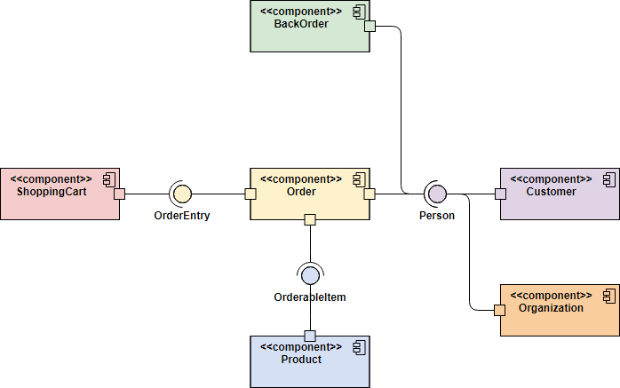
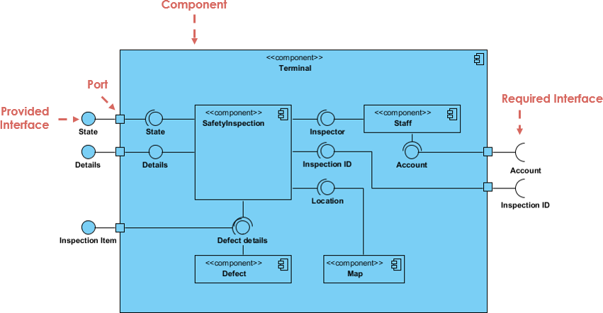
Data can not flow between two data stores. Components are drawn as the following diagram shows. They provide a high-level view of the components within a system.
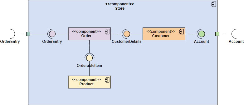
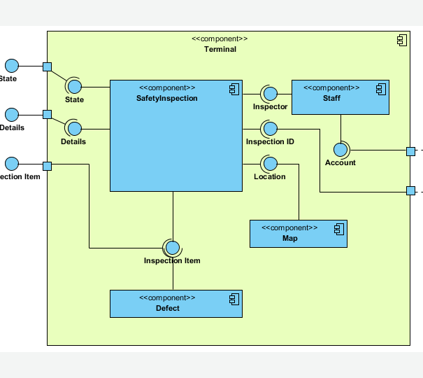
Following are the rules which are needed to keep in mind while drawing a DFD Data Flow Diagram. Graphically a component diagram is a collection of vertices and arcs and commonly contain components interfaces and dependency aggregation constraint generalization association and realization relationships. Component diagrams are often drawn to help model implementation details and double-check that every aspect of the systems required functions is covered by planned development.
Component diagrams are used to visualize the organization of system components and the dependency relationships between them. Or a business unit such as supplier. Dependency Realization Association Aggregation.
Select an Element where a new Component to be contained. Diagrams such as Figure 1 are often referred to as wiring diagrams because they show how the various software components are wired together to build your overall application. Select Model Add Component in Menu Bar or Add Component in Context Menu.
To create a Component. The component diagrams main purpose is to show the structural relationships between the components of a system. Drag on the diagram as the size of Component.
The components can be a software component such as a database or user interface. The Component diagram is one of the Unified Modeling Language Structural diagrams that can be used to model the logical components that make up a system. If one bulb goes.
 Component Diagram Tutorial
 Component Diagrams See Examples Learn What They Are
 Component Diagram Tutorial
 Component Diagram Tutorial
 Component Diagram Uml 2 Diagrams Uml Modeling Tool
 Component Diagrams See Examples Learn What They Are
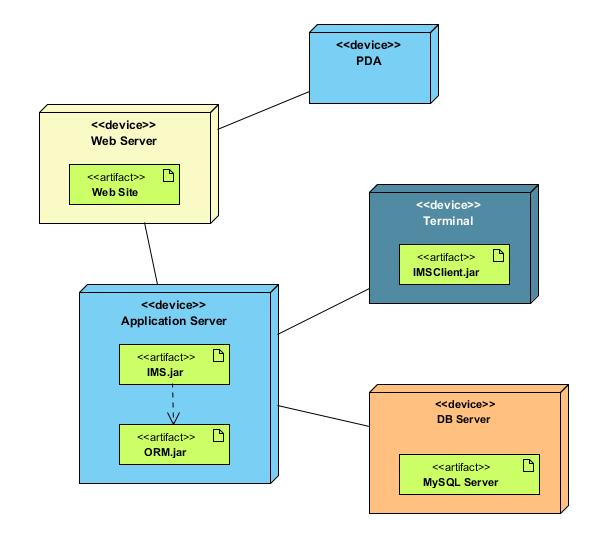 Deployment Diagram Uml 2 Diagrams Uml Modeling Tool
 A Comprehensive Guide To 14 Types Of Uml Diagram By Warren Lynch Medium
 Component Diagram Tutorial Lucidchart
 E Commerce Microservices Uml Deployment Diagram
 Deployment Diagram Tutorial Lucidchart
 Uml Component Diagram Example For A Content Management System Cms This Component Diagram Example Is Bro Component Diagram Diagram Content Management System
 A Comprehensive Guide To 14 Types Of Uml Diagram By Warren Lynch Medium
 Component Diagram Tutorial Lucidchart
 Component Diagram Tutorial
 Component Diagrams See Examples Learn What They Are
Component Diagram Tutorial
 Component Diagram Tutorial Lucidchart
 Component Diagram Tutorial Lucidchart


0 Commentaires