Use case diagram Class diagram Collaboration diagram Sequence diagram State chart diagram Activity diagram and Component diagram. From the Tools menu select Visual C then select Update Model from Code.
 Lms Deployment Diagram Uml Tutorial For Beginners
During the requirements phase we use the Rational Rose to develop use cases.
Component diagram rational rose. The component view contains a Main diagram by default. Modeling can be useful at any point in the application. Hal ini dibutuhkan ketika nanti akan melakukan generate code membuat contoh code dari design yang telah dibuat.
Creating Rose Class Diagram. This view contains information about the software executable and library components for the system. Rename Main to Class Diagram.
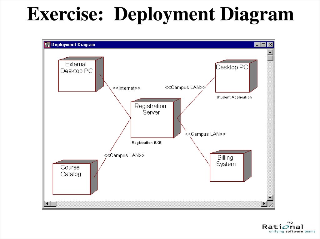
Use case View Logical View Component View dan Deployment View. Applications of Rational Rose Software. It is a professional and widely used in industry.
1 Rational Unified Proses RUP merupakan. The use case diagrams are stored in the Use Case View folder. The Rose 7004 iFix001 Release Notes download below includes information describing any known issues and the fixes included.
Double-click on Class Diagram to display the class diagram. Views pada Rational Rose 321. In academics rational rose software helps in making the diagram during the design phase of software development life cycle.
Visual Modeling With Rational Rose 2000 And UML 2. Create or open a component diagram. UML memiliki beberapa tipe diagram yang berbeda yang dapat digunakan untuk mengkombinasi dalam menyusun semua dari sebuah sistem.
ROSE Rational Object Oriented Software Engineering Rational Rose is a set of visual modeling tools for development of object oriented software. Use case diagram Sequence diagram Collaboration diagram Activity Diagram Class Diagram Statechart Diagram Component Diagram dan Deployment Diagram. Diagram merupakan graph yang menjelaskan tentang isi dari sebuah view.
Visual Modeling with Rational Rose. IBM Rational Rose Enterprise 7004 iFix001 includes fixes for the following Rose components. Facilitates use of the Unified Modeling Language UML Component Object Modeling.
Graphical User Interface GUI pada Rational Rose 34. Diagram pada Rational Rose 341. Sebutkan komponen dari Use Case Diagram.
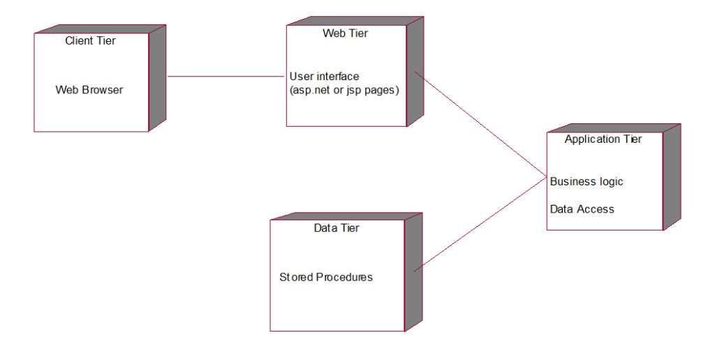
The component view addresses the software organization of the system. Apa itu Rational Rose 32. Rational rose software is basically used to draw UML diagram.
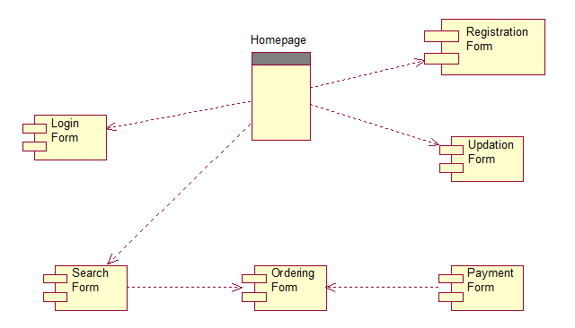
Pengenalan Dasar Rational Rose 311. They show the organization and dependencies among software components including source code binary code and executable components. Place classes on the diagram.
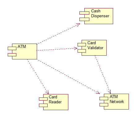
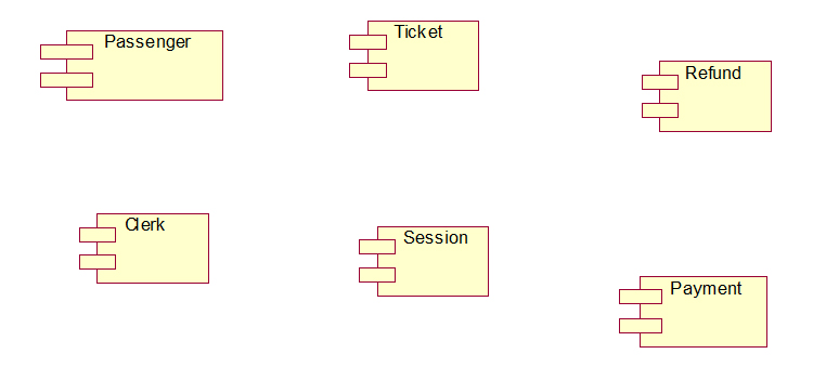
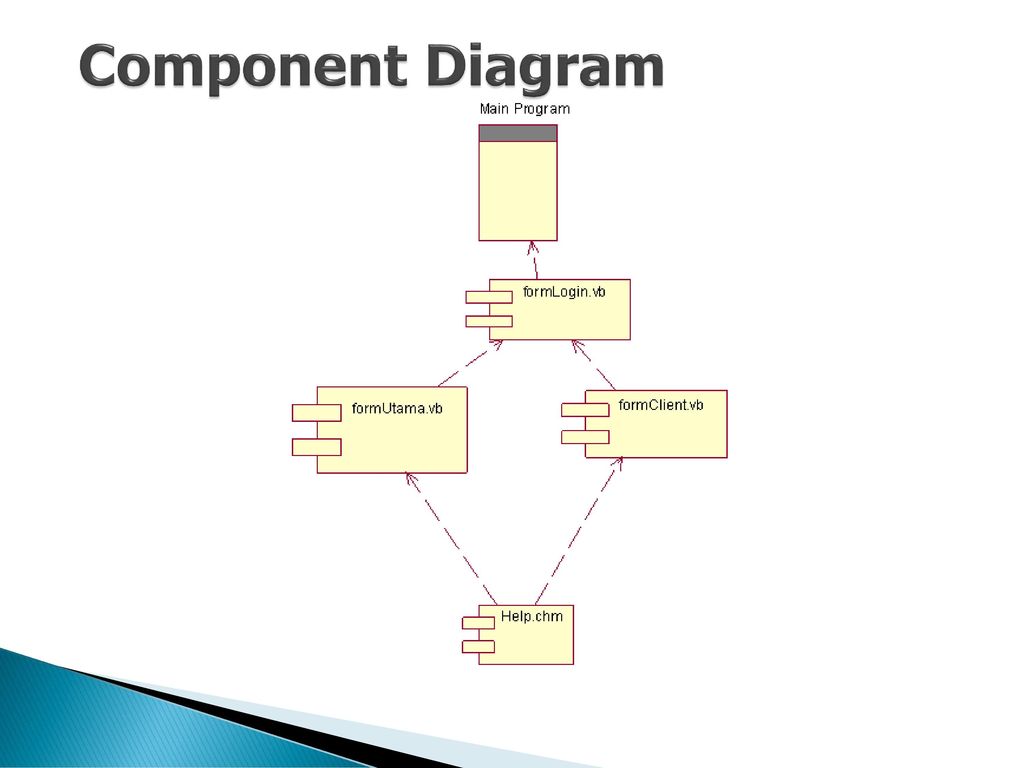
COMPONENT DIAGRAM Nama Komponen Keterangan Simbol Component Sebuah komponen melambangkan sebuah entitas software dalam sebuah sistem. Use Case Diagram 342. Rational Rose 2000 memiliki delapan diagram yaitu.
UML memiliki beberapa tipe diagram yang berbeda yang dapat digunakan untuk mengkombinasi dalam menyusun semua dari sebuah sistem. Rational Rose is the visual modeling software solution that lets you create analyze design view modify and manipulate components. UML DENGAN RATIONAL ROSE Daftar Isi 31.
Rose uses the UML to provide graphical methods for non-programmers wanting to model business processes as well as programmers modeling application logic. To enter an attribute select a class then press Right Mouse. Use case diagram Sequence diagram Collaboration diagram Activity Diagram Class Diagram Statechart Diagram Component Diagram dan Deployment Diagram.
Open a new model in Rational Rose. Sebuah komponen dinotasikan sebagai sebuah kotak segiempat dengan dua kotak kecil tambahan yang menempel disebelah kirinya. You can create one or more component diagrams to depict components and.
Database Rational Unified Process RUP VB6 Standard serta model-model yang lain. Rational rose memiliki empat view yaitu. UML memiliki beberapa tipe diagram yang berbeda yang dapat digunakan untuk mengkombinasi dalam menyusun semua dari sebuah sistem.
Model-model ini merupakan pilihan apakah ingin membuat file Rational Rose yang mengandung komponen Java Visual Basic atau Visual C. This view contains only component diagrams. Rational Rose 2000 memiliki delapan diagram yaitu.
In Browser Window select Logical View. You can graphically depict an overview of the behavior of your system with a use-case diagram. Introduction to Rational Rose 37 Component diagrams Component diagrams provide a physical view of the current model.
The Diagram given below shows the Logical View of Rational Rose. A use case diagram provides a functional specification of a system and its major processes and describes the problem that needs to be solved. To create a new diagram right-click on the Component View folder select New and then select Component Diagram.
Rational Rose provides the collaboration diagram as an alternative to a use-case diagram.
 Component Diagram Of System Download Scientific Diagram
 Component Diagram Describing The Architecture Download Scientific Diagram
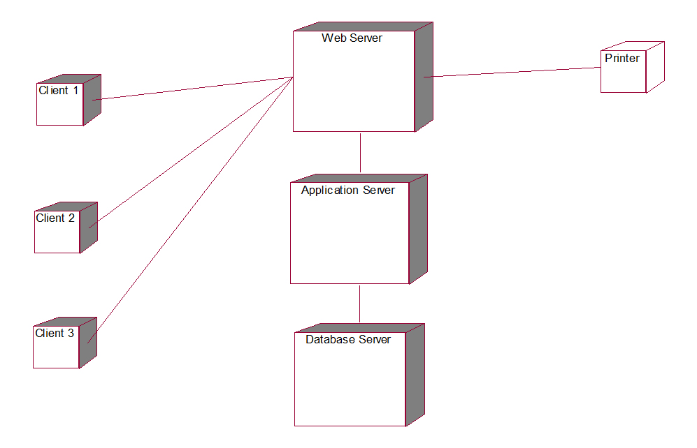 Rrs Deployment Diagram Uml Tutorial For Beginners
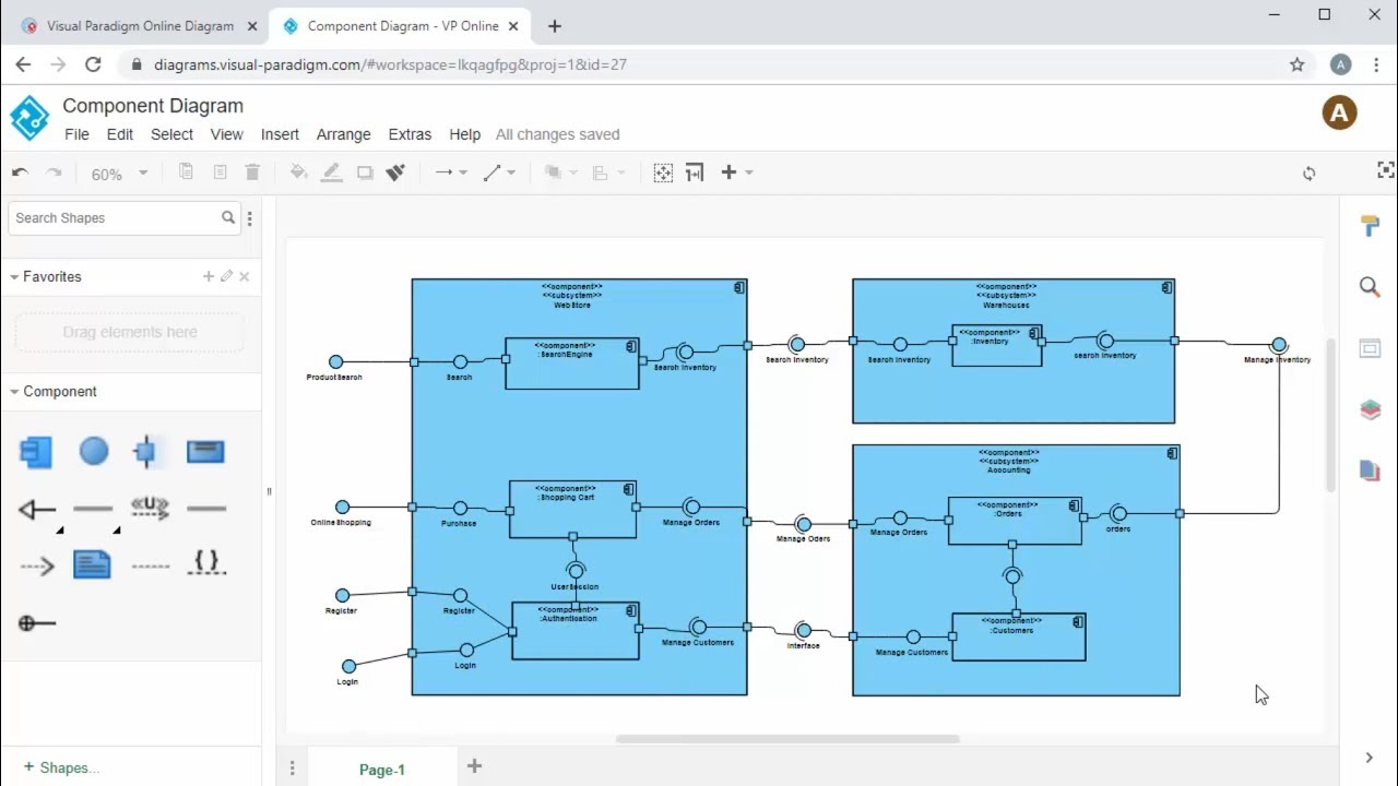 Create Component Diagram Online Youtube
 Data Warehouse Physical Schema Component Diagram Part 1 Download Scientific Diagram
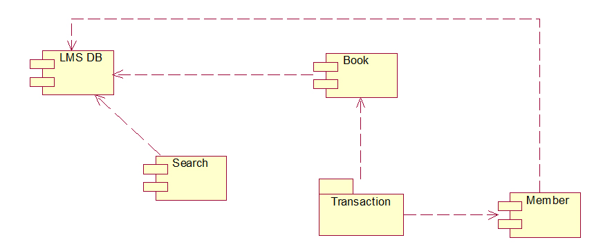 Lms Component Diagram Uml Tutorial For Beginners
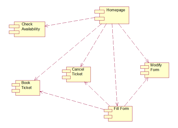
 Obns Component Diagram Uml Tutorial For Beginners
 Rrs Component Diagram View Classes Uml Tutorial For Beginners
 Component Diagram Of System Download Scientific Diagram
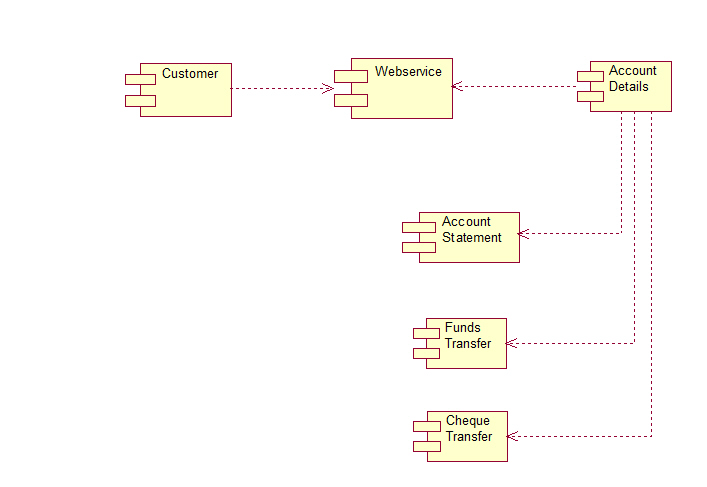
Atm Component Diagram Uml Tutorial For Beginners
 Architectural View Siti Mukaromah S Kom Ppt Download
 Introduction To Uml Online Presentation
 4 Create Deployment Diagram Using Rational Rose Youtube
 Component Diagram Of System Download Scientific Diagram
Http Www Uop Edu Pk Ocontents Online 20bookshop 20uml 20diagrams Pdf
 Uml Component And Deployment Diagrams On Atm Transactions Youtube
 Uml Diagrams For Payroll Processing System Gatelockservice


0 Commentaires