Feedback Control Systems FCS Lecture-8-9 Block Diagram Representation of Control Systems Dr. A The manual steering system of an automobile b Drebbels incubator c The water level controlled by a float and valve d Watts steam engine with fly-ball governor.
 Negative Feedback And Negative Feedback Systems
Imtiazhussainfacultymuetedupk URL ht Slideshare uses cookies to improve functionality and performance and to provide you with relevant advertising.

Draw a component block diagram for each of the following feedback control systems. Here two blocks. This is the simplified block diagram. The functional block represents the elements or components of the control system.
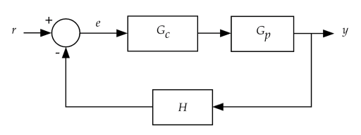
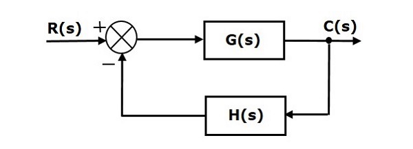
Problem 1P from Chapter 1. The above block diagram consists of two blocks having transfer functions Gs and Hs. Problem 101PP Draw a component block diagram for each of the following feedback control systems a The manual steering system of an automobile b Drebbels incubator c The water level controlled by a float and valve d Watts steam engine with fly-bail governor In each case indicate the location of the elements listed below and give the units associated.
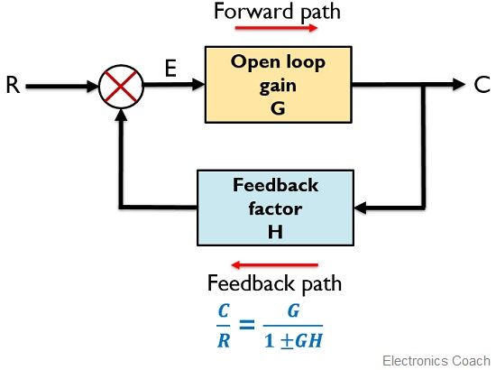
The following figure shows negative feedback control system. Assignment 1 Draw The Component Block Diagram For Each Of The Following Common Feedback Control Systems. If the transfer function of input of control system is Rs and the corresponding output is Cs and.
Draw a component block diagram for each of the following feedback control systems. Feedback control - 87 832 Manipulating Block Diagrams A block diagram for a system is not unique meaning that it may be manipulated into new forms. This feedback loop helps to provide a part of the input back to the input.
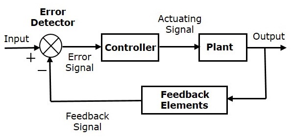
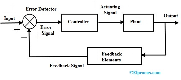
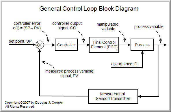
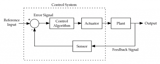
Identify Controller Actuator Process And Sensor As Shown In The Example Below. 3 shows the general block diagram for a system with feedback control. The block normally contains the name of the element Figure 1B or the.
EXAMPLE PROBLEMS AND SOLUTIONS A-3-1. Control Systems - Block Diagram Algebra - Block diagram algebra is nothing but the algebra involved with the basic elements of the block diagram. Assignment 1 Draw The Component Block Diagram For Each Of The Following Common Feedback Control.
First move the branch point of the path involving HI outside the loop involving H as shown in Figure 3-43aThen eliminating two loops results in Figure 3-43bCombining two. 11 Draw a component block diagram for each of the following feedback control systems. The diagram will then be simplified through a process that is.
Basic Elements of Block Diagram. Block diagrams consist of Blocksthese represent subsystems typically modeled by and labeled with a transfer function Signals. A The manual steering system of an.
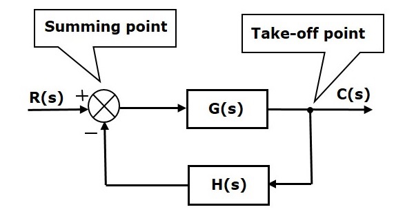
The basic elements of a block diagram are a block the summing point and the take-off point. For the successful implementation of this technique some rules for block diagram reduction to be followed. Let us discuss these rules one by one for the reduction of the control system block diagramIf youre looking to do some control systems study check out our control systems MCQs.
A block diagram provides a means to easily identify the functional relationships among the various components of a control system. 11 Draw a component block diagram for each of the following feedback control systems. It consists of a single block with one input and one output Figure 1A.
Draw a component block diagram for each of the following fee. Basically in block diagram representation each element of the control system is represented by a block. A The manual steering system of an automobile b Drebbels incubator c The water level controlled by.
As we discussed in previous chapters there are two types of feedback positive feedback and negative feedback. Simplify the block diagram shown in Figure 3-42. Step 5 Use Rule 1 for blocks connected in series.
View HW1-Problems from EECS 160a at University of California Irvine. Draw a component block diagram for each of the following feedback control systems. The modified block diagram is shown in the following figure.
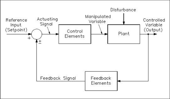
A The manual steering system of an automobile b Drebbels incubator c The water level controlled by a float and valve d Watts steam engine with fly-ball governor In each case indicate the location of the elements listed below and give the units. Typically a block diagram will be developed for a system. Let us consider the block diagram of a closed loop control system as shown in the following figure to identify these elements.
The simplest form of a block diagram is the block and arrows diagram. Feedback refers to the returning of the measurements of a controlled variable to the controller so that it can be further used to influence the controlled variable. The modified block diagram is shown in the following figure.
The modified block diagram is shown in the following figure. Webb MAE 4421 3 Block Diagrams In the introductory section we saw examples of block diagrams to represent systems eg. Feedback Control Of Dynamic Systems 7th Edition Edit edition.
Step 6 Use Rule 3 for blocks connected in feedback loop. Elements of Block Diagram. Control signal from the controller as an input and outputs the variable being controlled.
 Block Diagram Of Cnc Machine Tool Control System Download Scientific Diagram
 Control Systems Quick Guide Tutorialspoint
 Control Systems Part 2
 Control System Basics Ledin Engineering Inc
 Control Systems Block Diagrams Tutorialspoint
On Off Control System X Engineer Org
 Block Diagram Of Cnc Machine Tool Control System Download Scientific Diagram
 Closed Loop Control System Block Diagram Types Its Applications
 Wescott Design Services Using Block Diagrams
 Block Diagram Representation Of Control Systems
 Feedback Systems And Feedback Control Systems
 System Block Diagram An Overview Sciencedirect Topics
 The Basics Of Process Control Diagrams Technology Transfer Services
 What Is Feedback System Block Diagram And Types Of Feedback Electronics Coach
 Block Flow Diagram Of A Feedback Control And B Feedforward Control Download Scientific Diagram
 Control System Basics Ledin Engineering Inc
 Control Systems Quick Guide Tutorialspoint
 7 General Block Diagram Of Control Loops A Open Loop And B Closed Download Scientific Diagram


0 Commentaires